WELCOME TO THE RYAN RUTLEDGE JOHN DEERE MODEL H FARM TRACTOR RESTORATION

This is a project to restore a John Deere 1940 model H farm tractor that belonged to Ryan Rutledge's great grandfather James Carpenter.

Web site manager: Eugene (Gene) D. Johnson, Ryan's grandfather.
446 Trinity Drive, Allen, TX 75002
469-675-1316
This web page was initiated November 17, 2004, and last up-dated February 12, 2006.


Here is the young farmer boy now:


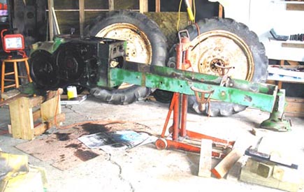
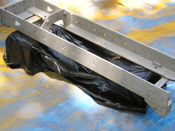
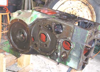
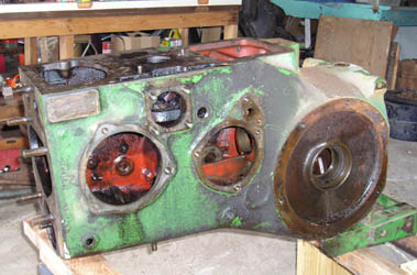
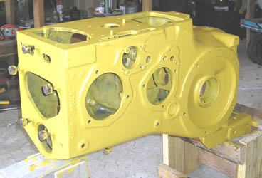
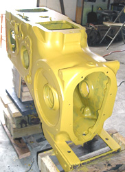
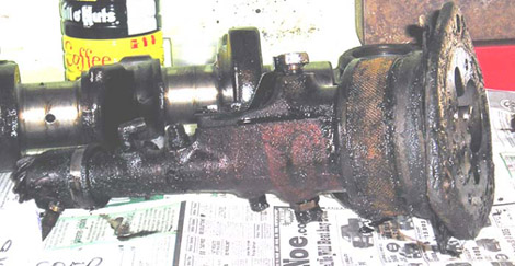
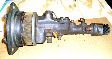
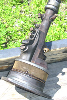
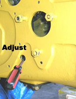
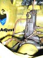
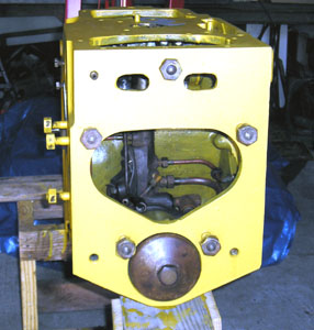
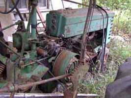
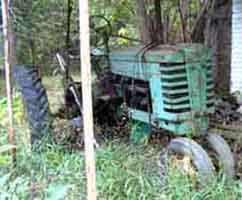
The following pictures represent the "before" condition of the tractor:


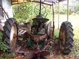
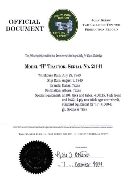
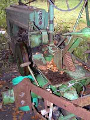
The John Deere (JD) model H tractor was introduced in 1939, starting with serial number 1000. The tractor being restored has serial number 21141, so, it was the 20,141th model H built.

The communication I have had, via the internet and by telephone, with others who have knowledge of this tractor tell me that during the first couple of years of a new tractor release, JD made undocumented changes on the production line that may not be reflected in the parts and service manuals. Their only comment on this was to check to see that what is on the tractor matches the parts and service manual. BTW, I was able to order these manuals (owners and parts) from JD on a CD. I have also ordered an Implement and Tractor (IT) service manual via eBay.

Mr. Carpenter acquired the tractor in about 1970 as payment for some work preformed for the previous tractor owner. He used it occasionally to plow land for a spring garden.

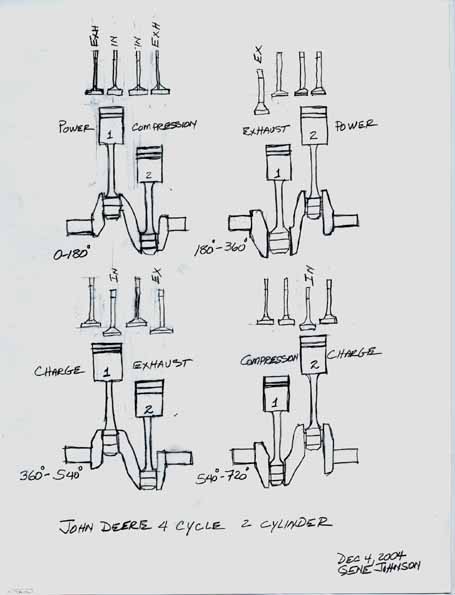
My first inspection of the tractor showed that the engine turned over easily with the clutch disengaged by manually rotating the flywheel toward the front (counter clockwise). While doing this, I was able to feel the resistance of the compression cycle indicating that there was at least some compression. This is an indication of the condition of the piston rings and valves.

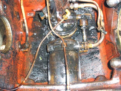
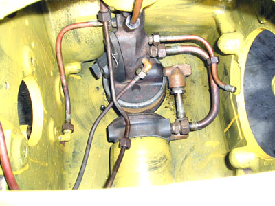
I observed that there was an automotive engine coil and condenser wired into the magneto. This modification was added on later and not the original electrical circuit. It was probably done to save the cost of a magneto repair and/or the need to keep the tractor working during a critical period in the cycle of farming. .

The early farm tractors and also cars used magnetos to provide an electrical charge to the sparkplugs. The magneto consists of a coil, a capacitor, and a set of points to open and close the circuit. When the points are opened as the engine is hand cranked, the capacitor will discharge to the plug firing the air/fuel mixture in the cylinder.

Today’s tractors and cars use an electric starting system powered by a battery and a started motor. This option was available in 1939 however the option was not put on this tractor.

Last Monday (November 8) I sent the magneto to a shop Iowa for repair but have now learned that it cannot be repaired but must be replaced. Fortunately there is a company that still makes a similar version that will work so I have ordered the new one.

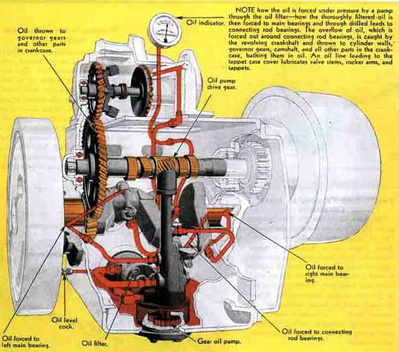
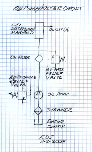
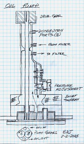
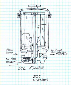
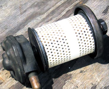
I have also ordered an engine oil filter and have purchased SAE 40 weight non-detergent oil. I have decided to use heavier weight oil (SAE 40) to compensate for engine wear. The operation manual calls for SAE 30 weight oil. I was able to find non-detergent oil which is what would have been used originally. The detergent oils came about in more recent years with the high performance automotive engines that run at high temperatures and operate at several thousand revolutions per minute (RPM). The operating speed for this tractor at full load is only 1400 RPM (1700 RPM can be achieved using the foot pedal for higher road speed). Plus, adding detergent oil now would loosen all the sludge that has accumulated over the years and quickly plug the filter. At this point, this sludge should not be free to get into the working parts.

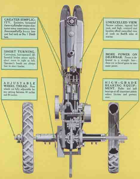
I also notice that there is no water pump or thermostat. The cooling water is circulated via convection due to the heat difference across the radiator. John Deere advertised this as “Thermosyphon” cooling. The engine operating temperature is maintained by the operator using mechanical shutters on the radiator. Desired operating temberature is 190 degrees Fahrenheit. Although, it doesn’t look like this tractor is equipped with shutters. They probably weren’t necessary in Texas.

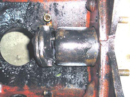
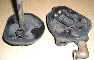
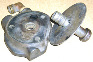
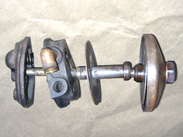
The engine air filter is an oil bath design using engine oil.

December 3, 2004

The following is an update on progress of getting the tractor started so it can be driven into the garage.

to do list:

Remove plow (complete)
Remove battery bracket (complete)
Use penetrating oil on spark plugs and remove (complete)
Drain engine oil (complete)
Remove/replace oil filter (complete)
Remove/Clean oil breather filter (complete)
Add new engine oil filter and gasket (complete)
Add engine oil (complete)
Remove/clean air intake filter cup
Replace power lift reservoir oil (complete)
Install magneto (complete)
Add ground wire to magneto to stop tractor
Check for water plug in head and add water (complete)
Add fuel (1 gallon) and check for leaks (complete)

When adding water, a gasket leak at the connection of the pipe to the top of the radiator was noted. This will be repaired later. The engine covers need to be removed to access this. However, there is enough water in the engine to run the tractor for a short period of time. I also added a half gallon of anti-freeze.

When adding gasoline, the filter sight glass filled and the fuel system seems to be tight with the exception of a small leak at the sight glass gasket.

Was not able to get the tractor started Saturday (December 4) and now will inspect the carburetor on my next visit to see if the float is working properly to shut off the fuel.

I drew the following sketch showing the different stages of the four cycle two cylinder engine at 180 degree increments. In order to have a balanced crankshaft, the two cylinders must fire 180 degrees apart. Then, cylinder number one doesn’t fire again until there is one complete revolution of the crankshaft. The inertia of the heavy flywheel attached to the crankshaft helps "carry" the crankshaft through this “dead” revolution. This is also what gives the John Deere two cylinder engine the distinctive acoustic exhaust sound and how they came to have the name “Johnny Popper”.

I have also copied a top-view cross section of the tractor showing some of the internal parts of the engine and transmission. It is interesting to see that the pulley and transmission are powered by the camshaft which rotates at half engine speed. The pulley is directly connected with a spline drive on the camshaft. A spur gear on the cam shaft is the second of the three gear reductions to the differential.


Entry dated January 31, 2005

After installing a new magneto, new plugs and wires and a rebuilt carburetor, I still was not able to get the tractor started. Sooo, I took another look at the timing procedure. While doing this, I noticed that the flywheel was installed onto the crank shaft one spline off. As there are 10 splines, this would cause the timing to be off 36 degrees. Timing is established with marks on the flywheel and case.

After I retimed the magneto, compensating for the 36 degrees, I was able to get the tractor to fire but not run. This was ultimately traced to the fact that the three way fuel valve was incorrectly installed so that the off position was actually the on position for the “Fuel” tank. This is an all fuel tractor and the three way valve will either open the large fuel tank the small gasoline tank or turn all off.

With the tractor running I was able to drive it into Mrs. Carpenter’s garage where I plan to do the restoration. There was considerable “blue” smoke in the exhaust which would be coming from the crankcase across the rings or valve stems. This will be resolved by removing the head, cylinders and pistons for inspection and repair as necessary.

Entry dated February 12, 2006

The last entry (January 31, 2005) detailed getting the tractor started and driving it into Mrs. Carpenter’s garage. That involved pulling the tractor with a pick-up which did get it started but it quickly died. Eventually it was discovered that the fuel valve was marked wrong. Turning the valve to “on” actually closed fuel to the carburetor. This was determined by disconnecting the lines out of the valve and turning it to the different positions. When the valve was in the “off” position it opened the line and supplied fuel to the carburetor. The tractor was able to start manually by rotating the flywheel.

It has been a year since the last entry. In that period of time, I have completely disassembled the tractor and have started reassembly. However, I haven’t worked on it since June, 2005. First due to the hot weather in the summer and now because I am undergoing a medical protocol for a rare disease called Sarcoidosis. I expect to start work on the tractor again this fall.


So now I will summarize the restoration as it stands today starting with some pictures at various stages of disassembly.


home